Articles & techniques
The Bulle coil
The coil in the pendulum bob is the heart of a Bulle. This page brings together what the restorations show about testing it, the faults that stop it working, and how it is rewound.
Testing the coil
The first check on any Bulle pendulum is a resistance reading with a meter that reads up to at least 2,000 ohms. Section 5 of Restoring a Bulle Clock gives the normal range as 1,000 to 1,300 ohms, with 1,100 ohms ideal. Bulle Nº 158805 quotes a slightly tighter working band of 1,050–1,250 ohms, measured between the contact pin and the suspension bracket.
The pendulum must be kept still while measuring. As the coil moves over the magnet it generates a small voltage of its own, which makes the reading wander (Bulle Nº 5937).
| Clock | Ohms | Notes |
|---|---|---|
| No-serial wall clock | 746 | Untouched original, early low-resistance coil |
| Nº 2022 | about 720 | Early coil; missing frame resistor remade |
| Nº 1491 | 1300 | Transitional: over-wound and heavy |
| Nº 3720 | 1150 | After rewinding with 6,500 turns of 42 SWG |
| Nº 6792 | 1103 | |
| Nº 11536 | 1140 | |
| Nº 186300 | 1170 | |
| Nº 201051 | about 800 → 1140 | Previously under-wound; extended by a couple of thousand turns |
| Nº 201191 | none → 1240 | Break at a soldered joint, re-soldered |
| Nº 252502 | 1145 | |
| Nº 274481 | 1243 | Measured at the contact pin |
Why the resistance matters
The coil’s resistance sets how much current flows each time the contact closes. On a 1.5 volt cell, Ohm’s law gives about 1.4 milliamps through an 1,100-ohm coil, but about 2.1 milliamps through a 700-ohm coil: half as much again. The notes for Nº 201051 put the effect of a low-resistance coil plainly: it “will give one hell of a swing, but short battery life.”
The earliest production clocks had coils of around 650–700 ohms. The notes for Bulle Nº 1583 suggest that this “must have been realised” to be too low, giving too great a swing and a shorter battery life, so a separate resistor was added between the battery and the coil on the frame. An original example measured 275 ohms, and Nº 776 is recorded as having a 700-ohm resistor to go with its 650-ohm coil, so the value probably varied to suit each coil. Later coils were wound to about 1,100–1,200 ohms and needed no extra resistor. Bulle Nº 1491, at 1,300 ohms and visibly heavier, appears to be from the changeover.
Common faults
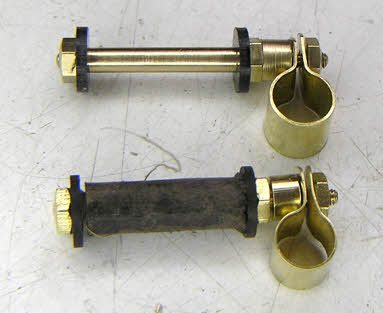
- Broken lead-out wires. The heavier wire joined to the fine winding is the usual weak point. The insulating tube it passes through can turn “as brittle as a dry biscuit”, letting the wire short to the casing. On Nº 7221 the notes explain that if the inner lead breaks with too little wire left to rejoin, the whole coil must be rewound.
- Corroded joints. On Nº 7446 the uninsulated copper lead soldered to the start of the winding had corroded. The same coil had also been drilled into by a pendulum rod screwed right through the brass shell.
- A hidden break. When a coil reads nothing at all, the fault may be at the inner joint, under all 6,500 turns (Nº 26561), or simply at an outer joint that can be re-soldered (Nº 201191).
- Tampering. Modern PVC or masking tape wrapped round the winding (Nº 313749, Nº 12019) and cut or extended lead-outs (Nº 67438) are signs that someone has been inside before.
Rewinding
A standard Bulle coil is rewound with about 6,500 turns of 42 SWG enamelled copper wire (Nº 3720, Nº 67438). 42 SWG is just 0.004 inch (0.1016 mm) in diameter.[1] Copper of that size has a resistance of roughly 2 ohms per metre[2], so an 1,100-ohm coil holds in the region of half a kilometre of wire.
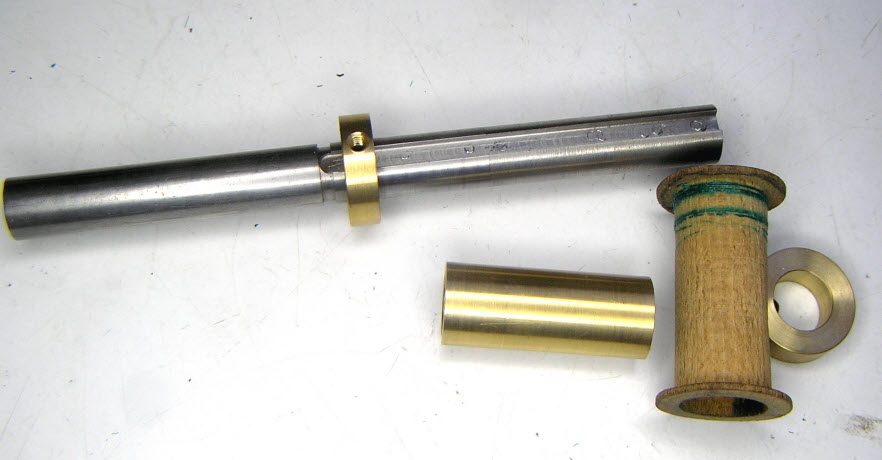
The fullest account is in the notes for Nº 7446. The bobbin is held on a stepped arbour in the lathe, with a collet that can either spin freely, to unwind an old coil, or be pinned so the bobbin turns with the spindle for winding. The feed spool sits behind the lathe. The start of the wire is anchored through the hole in the bobbin, and joints to the lead-out wires are cleaned, checked with the meter, soldered and wrapped in folded brown paper. Early coils are wound on wooden bobbins; Nº 27993 has a cardboard one.
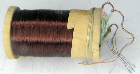
Twisted rather than soldered joints are sometimes preferred for the lead-out wires, because solder makes the joint too stiff to feed through the coil casing (Nº 12199). As section 5 of the guide says, if you lack the tools and skill, it is better to have a coil rewound by a specialist.
The cord covering
The brass coil casing is traditionally bound in green cord. Where the original is sound, it is protected with low-tack masking tape while the brass is cleaned (Nº 12199, Nº 57470). Old cord cannot simply be unwound and rewound, because the inner face has faded less than the outer and a criss-cross pattern results. Where it has to be replaced, new cord is used, such as “Gutterman 237” on Nº 6792.
Sources
Workshop methods, readings and quotations are from the Horologix restoration notes linked above. Other information is from:
- Standard wire gauge (table of SWG sizes). Wikipedia. https://en.wikipedia.org/wiki/Standard_wire_gauge
- Electrical resistivity and conductivity (value for copper). Wikipedia. https://en.wikipedia.org/wiki/Electrical_resistivity_and_conductivity